Pic : Model Unified Power Flow Controller
1.Circuit Description
A UPFC is used to
control the power flow in a 500 kV /230 kV transmission system. The system,
connected in a loop configuration, consists essentially of five buses (B1 to
B5) interconnected through transmission lines (L1, L2, L3) and two 500 kV/230
kV transformer banks Tr1 and Tr2. Two power plants located on the 230-kV system
generate a total of 1500 MW which is transmitted to a 500-kV 15000-MVA
equivalent and to a 200-MW load connected at bus B3. The plant models include a
speed regulator, an excitation system as well as a power system stabilizer
(PSS). In normal operation, most of the 1200-MW generation capacity of power
plant #2 is exported to the 500-kV equivalent through three 400-MVA
transformers connected between buses B4 and B5. For this demo we are
considering a contingency case where only two transformers out of three are
available (Tr2= 2*400 MVA = 800 MVA).
Using the load flow
option of the powergui block, the model has been initialized with plants #1 and
#2 generating respectively 500 MW and 1000 MW and the UPFC out of service
(Bypass breaker closed). The resulting power flow obtained at buses B1 to B5 is
indicated by red numbers on the circuit diagram. The load flow shows that most
of the power generated by plant #2 is transmitted through the 800-MVA
transformer bank (899 MW out of 1000 MW), the rest (101 MW), circulating in the
loop. Transformer Tr2 is therefore overloaded by 99 MVA. The demonstration
illustrates how the UPFC can relieve this power congestion.
The UPFC located at
the right end of line L2 is used to control the active and reactive powers at
the 500-kV bus B3, as well as the voltage at bus B_UPFC. It consists of a
phasor model of two 100-MVA, IGBT-based, converters (one connected in shunt and
one connected in series and both interconnected through a DC bus on the DC side
and to the AC power system, through coupling reactors and transformers).
Parameters of the UPFC power components are given in the dialog box. The series
converter can inject a maximum of 10% of nominal line-to-ground voltage (28.87
kV) in series with line L2. The blue numbers on the diagram show the power flow
with the UPFC in service and controlling the B3 active and reactive powers
respectively at 687 MW and -27 Mvar.
2.Demonstration
2.1. Power control
with the UPFC
Open the UPFC dialog
box and select "Display Control parameters (series converter)". The
control parameters of the series converter are displayed.Verify that "Mode
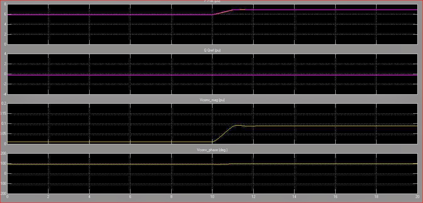
of operation = Power flow control". The UPFC reference active and reactive
powers are set in the magenta blocks labeled "Pref(pu)" and
"Qref(pu)". Initially the Bypass breaker is closed and the resulting
natural power flow at bus B3 is 587 MW and -27 Mvar. The Pref block is
programmed with an initial active power of 5.87 pu corresponding to the natural
flow. Then, at t=10s, Pref is increased by 1 pu (100 MW), from 5.87 pu to 6.87
pu, while Qref is kept constant at -0.27 pu.
Run the simulation
and look on the "UPFC" scope how P and Q measured at bus B3 follow
the reference values. At t=5 s, when the Bypass breaker is opened the natural
power is diverted from the Bypass breaker to the UPFC series branch without
noticeable transient. At t=10 s, the power increases at a rate of 1 pu/s. It
takes one second for the power to increase to 687 MW. This 100 MW increase of
active power at bus B3 is achieved by injecting a series voltage of 0.089 pu
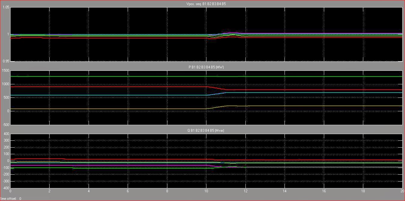
with an angle of 94 degrees. This results in an approximate 100 MW decrease in
the active power flowing through Tr2 (from 899 MW to 796 MW), which now carries
an acceptable load. See the variations of active powers at buses B1 to B5 on
the "VPQ Lines" scope.
 |
|
Pic : Unified Power Flow Controller Out put Measurement
|
|
2.2. UPFC P-Q
controllable region
Now, open the UPFC
dialog box and select "Show Control parameters (series converter)".
Select "Mode of operation= Manual Voltage injection". In this control
mode the voltage generated by the series inverter is controlled by two external
signals Vd, Vq multiplexed at the "Vdqref" input and generated in the
Vdqref magenta block. For the first five seconds the Bypass breaker stays
closed, so that the PQ trajectory stays at the (-27Mvar, 587 MW) point. Then
when the breaker opens, the magnitude of the injected series voltage is ramped,
from 0.0094 to 0.1 pu. At 10 s, the angle of the injected voltage starts
varying at a rate of 45 deg./s.
Run the simulation
and look on the "UPFC" scope the P and Q signals who vary according
to the changing phase of the injected voltage. At the end of the simulation,
double-click on the blue block located at the bottom right of the model. The
trajectory of the UPFC reactive power as function of its active power, measured
at bus B3 will be displayed. The area located inside the ellipse represents the
UPFC controllable region.
Where the voltage of each bus : Where the power of each bus :
V_B1 = 0,9967 pu P_B1 = 196,6 MW
V_B2 = 1,002 pu P_B2 = 689,7 MW
V_B3 = 1,001 pu P_B3 = 687 MW
V_B4 = 0,9942 pu P_B2 = 796 MW
V_B5 = 1,9989 pu P_B2 = 1277 MW
 |
Pic : V P Q out put measurements
That's
all from me, Hopefully useful ... Thanks
By : Sibuea Mark Quark Gluon Tao ( Lungguk Yusri'al Sibuea)
|
| 


0 komentar:
Posting Komentar