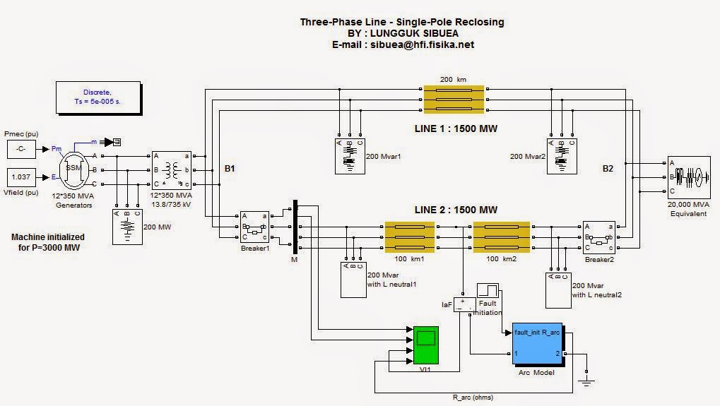
This demonstration ilustrates the use of
three-phase blocks to study phase-to-ground fault and single-pole reclosing of
a 735-kV transmission line.
 |
Pic : MODEL In SIMULINK MATLAB |
Circuit Description
Two
735 kV parallel lines, 200 km long, transmit 3000 MW of power from a generation
plant (12 generators of 350 MVA) to to an equivalent network having a short
circuit level of 20 GVA. The generation plant is simulated with a simplified
synchronous machine (subtransient reactance of 0.22 pu). The machine is
connected to the transmission network through a 13.8 kV/ 735 kV Wye-Delta
transformer.
The
line models are distributed parameter lines. The lines are assumed to be
transposed and their parameters R,L,C /km are specified in positive- and
zero-sequence components. Each line is shunt compensated by two shunt reactors
of 200 Mvars each, connected at line ends. Applying single pole reclosing at
this voltage level is made possible by the use of neutral inductances for the
two shunt reactances of line 2. Otherwise, the 'secondary arc current' which is
induced into the fault ( mainly because of the capacitive coupling between the
two sound phases and the faulted phase) would be too high to allow arc
extinction after opening of line breakers on the faulted phase. If you open the
two shunt reactance blocks of line 2, observe how the optimum neutral
inductance is calculated.
A
phase-to-ground fault is applied at the middle of line 2. In order to apply the
fault along the line, this line is simulated in two sections of 100 km. As soon
as the fault is detected by the protection relays (not simulated here) , an
opening command is sent to the two line breakers of the faulted phase. The
breaker are kept open during a certain 'dead time' , usually around 0.5 s,
during which the arc normally extinguishes, then the two breakers are reclosed
When
the two line breakers are tripped on the faulted phase, the fault current is
interrupted but a small current will continue to flow through the arc. If this
secondary arc current is too large (typically above 50 A), the arc cannot
extinguish and the breaker will reclose on the fault.
The
arc is modelled by a fixed or non-linear resistance R = f(Iarc_rms). The arc
extinguishes when its rms current falls below a certain threshold value
(typically 50 A) defined in the arc model block. Open the Arc Model block and
look at the arc parameters. The mean arc resistance is programmed as an
exponential function of the rms current. The mean arc resistance increases when
the rms arc current decreases so that the time for arc current to decay below
the threshold value is shortened . (With the specified parameters, Rarc =
0.1ohm and 30 ohms respectively for currents of 1kA and 100A). The Arc Model
block is a masked block. Use 'Look under mask' to see how the arc model is
implemented.
Open
the blocks simulating the two line breakers. See how the line opening/reclosing
sequence is programmed. The fault is applied at t = 1 cycle. Then, the opening
command is sent to both breakers at t = 4 cycles (3 cycles detection + opening
time). The two breakers are reclosed at t = 34 cycles after a dead time of 30
cycles, during which the arc creating the fault should extinguish.
Choose
Simulation/Start and observe the voltage and current waveforms on the 4-trace
oscilloscope. Observe the three phase-to-ground voltages and currents at
sending end of line 2 and the current flowing into the fault. The line voltages
and currents are measured with the 3-phase measurement bus of the Extras
library. It allows to output voltages and currents directly in pu. The machine
has been previously initialized to deliver 3000 MW of power at 1 pu voltage
(with the Load Flow option of the Powergui). The line currents flowing into
each line are therefore 15pu/100 MVA as observed on trace 2.
The
fault current (I_arc) is measured in amperes. It reaches 22 kA during the first
cycle, then it drops to a very small value after 3 cycles when the two line
breakers open. Use Y-zoom to look at the secondary arc current. It contains a
slowly decaying DC component and a fundamental component (12 A peak). As its
rms value is below 50 A, the arc extinguishes at the first current zero
crossing.
Now, open the Arc Model block menu and change
the arc model to a fixed resistance (0.1 ohm). Restart the simulation. Notice
that the DC component of the arc current prevents arc extinction, so that the
line is now reclosed on a fault. You can also suppress the neutral reactance in
the two shunt reactance blocks and see the impact on the secondary arc current.
 |
| Graphic ( SIBUEA MARK QUARK GLUON TAO ) |


0 komentar:
Posting Komentar